DIY Auto Top Off with Solid State Relay

The friendliest place on the web for anyone with an interest in aquariums or fish keeping!
If you have answers, please help by responding to the unanswered posts.

Serge

Aquarium Advice Addict
Joined
Nov 9, 2004
Messages
1,439
Location
Rockland, Ontario
Hey folks, I was rather quiet since I returned from vacation, but I was not idle. I got rather tired of running down and up the basement to start/stop my RODI water production, so I built myself a solid state relay (SSR). It uses a handful of parts, is relatively easy to assemble and can be controlled from either downstair or upstair and can also be set to run automaticaly with float switchs.

If anyone would be interested, let me know and I will post the schematic, explanations and a few pics.

8)
 
OK folks, I will now awaken this thread. My schematics have been updated and I have enough documentation to start posting stuff here. So it begins..... :mrgreen:

As I will progress with this, please feel free to comment or post questions. I will answer as time will allow me. Enjoy!

8)
 
INTRODUCTION

As with many things in life, necessity is the mother of many innovations/inventions. In this particular case, I modified electronic circuits, available on the internet, to suit my personal requirements. My requirements were pretty simple:

Easy to build, minimum amount of parts, reliable, no mechanical relay, keep the 120 Vac away from the salt water area, have visual indication when things are on or off and have remote control of the RO/DI system located in the basement.


8)
 
Unfortunately, I do have to include the section below.

LEGAL DISCLAIMER

I do NOT own rights/patents to any of the circuits or parts thereof, all the original information was obtained from the internet. This was built for my personal use, I am merely sharing this information with others DIY enthusiasts, FREE of charges, for the sake of making this hobby a little easier to manage end enjoy.

Should you decide to build this controller system, you are on your own. I am not and will not be responsible in any way, shape or form for what you do and how you use the information provided. In other words, if you decide to build this, by using the information provided, you agree that I am not and will not be responsible, you assume any and all responsibility, causes, effects, disaster, whatever, that may or may not occur. After assembling this little circuit, it may or may not work for you.

As with anything involving live household voltage/current, one must be diligent and apply the required caution that live AC commands. If you do not know what you are doing, or are not knowledgeable enough, in the fields of electronics or household electricity, do not attempt to build this. Otherwise, enlist the help/assistance of someone that is.

The only thing I can guarantee is that, after spending weeks of bread boarding, integrating, testing and debugging, I have build a working system and it works fine for me.

That being said now, I hope it will be useful for you and will, indeed, make your hobby more enjoyable.

END OF LEGAL DISCLAIMER


8)
 
PRINCIPLE OF OPERATION


When the container is filled at the maximum desired level, both float switches, FL1 and FL2, will be in the "open state". Meaning there is no current flowing through it. As water evaporates, the water level in the container will go down.

When water level gets below a certain level, float switch FL1 will be in the "closed state" allowing current to flow through it. At this point, nothing happens yet, except that the circuit is now ready for action.

Later on, water will go down to a certain level that will also place switch FL2 in the "closed state" allowing current flow. When this happens, the pump will start running to push water where you want it. Either RO/DI water from your prepared water container to your tank, or as in my case, it will activate a solenoid that directly feeds the RO/DI unit, which is connected to a very long plastic tube, which fills up my sump. As the water level rises in the sump, switch FL2 will eventually change to the "open state", but water will continue to flow until the level is high enough to change switch FL1 to the "open state". At this point, the circuit is reset, the pump/solenoid stops until the next time the water level is low enough to activate switch FL2 (closed state).

This is it! This is the basic principle of operation of my automated top off controller. Now, on with the manual modes of this gizmo.


8)
 
LOCAL CONTROL IN BASEMENT

If you would like to fill a container with RO/DI, while you are in the basement, it is easy. The only requirement is that you have a Tee connector and two valves, to redirect the water output to your local water line in the basement. Piece of cake! Open the valve for downstairs output, close the valve for upstairs output, and turn on switch S4 to activate your pump/solenoid. LED D1 will turn on and voila! Sit tight and wait or check later. Do not forget to switch back your two valves when you are done!!

8)
 
REMOTE CONTROL UPSTAIRS

If you would like to fill a container with RO/DI, it is the same principle as explained in the previous paragraph with a few differences. You still require a Tee connector and two valves. One output will be to your sump (normal operation) and the other will be use for manual output. Close the valve for normal operation, open the other valve and turn on switch S3. LED D6 will turn on and your pump/solenoid, downstairs will start. When done, turn off switch S3 and switch back your valves.

NOTE

If you do not desire to have one or the other, or any of the manual features, later I will list the parts that you can skip.

8)
 
I will have additional details and information to post later, so please bear with me and do not build this thing before you have all the details. I will let you know when I have posted all the information that you need. :mrgreen:

In the meantime, print and review the schematics to understand how they relate to one another. Have fun!! :mrgreen:

8)
 
deffintely need to print them all out to see the links together but my first question...

why the time circuit?
 
BillyZ said:
deffintely need to print them all out to see the links together but my first question...

why the time circuit?
The 555 is used as a bistable oscillator. Meaning that it only has two states: ON or OFF. In this circuit, it's main purpose is to act as a "bounce free" switch. You know, as water is flowing it makes waves and would cause erratic operation of the rest of the circuit.

When switch FL2 is activated, the circuit stays on until switch FL1 is off. While between the low level (trigger point) and the high level (reset/off point), it does not matter if the water surface makes the switch go ON and OFF, once it's on it stays on until the reset point.

Is this clear enough? I have a tendency to say a lot when I explain. 8O Refer to my introduction about this topic. :wink:

8)
 
Bearfan said:
I have my autotopoff on a timer, otherwise it goes off and on constantly as the water moves.

Sounds like you definitely need my little circuit! :wink: What you are experiencing is "switch bouncing", which my little circuit prevents.

As you can see in my previous explanation above, this is one thing that this circuit will not do. Not to mention the fact that you can also burn your pump or solenoid.

Anyway, tag along until the rest of the details are posted. :D

8)
 
Here is the parts list folks. Most of the parts can be obtained from most electronics supplies store or mail order outfits.


PARTS LIST

RESISTORS: All ½ watt @ 2%
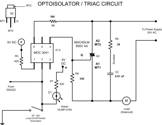
39 Ohms: R9
330 Ohms: R8
360 Ohms: R6
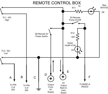
620 Ohms: R5, R7, R12
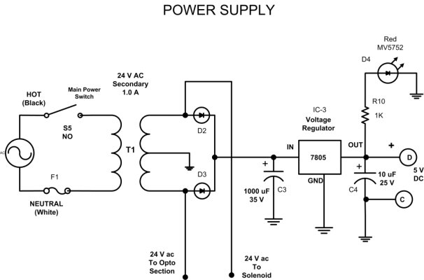
1 Kilo Ohms: R10, R11
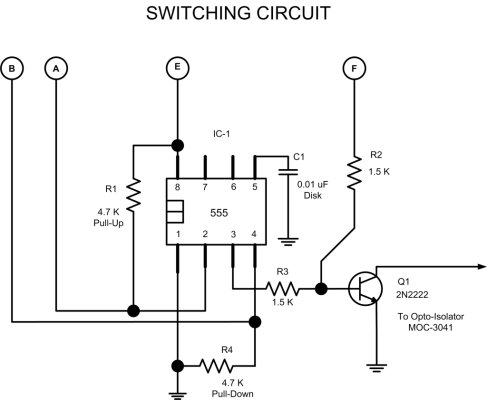
1.5 Kilo Ohms: R2, R3
4.7 Kilo Ohms: R1, R4


CAPACITORS:

C1: 0.01 Microfarad (Disk)
C2: 0.01 Microfarad @ 200 volts (Mylar)
C3: 1000 Microfarads @ 35 volts (Electrolytic)
C4: 10 Microfarads @ 25 volts (Electrolytic)


DISCREET DEVICES:

IC-1: 555 Timer Chip
IC-2: MOC3041 Optoisolator Triac Driver Chip
IC-3: 7805 Voltage Regulator Chip. Rated for 5 volts @ 1 Amp. Case Type: TO-220
Q1: 2N2222 NPN Transistor
Q2: MAC4DLM Triac Chip. Rated for 600 volts @ 4 amps. Case Type: 369D


DIODES/LED:

D1, D5: HLMP4740 Green LED
D4, D6: MV5752 Red LED
D2, D3: Rectifier Diodes. Rated for 125 volts @ 2 amps.

MISCELLANEOUS:

FL1, FL2: Reed Switches – Float Switches Normally Open (NO) Type

S1, S2, S3, S4: Small Toggle Switches – SPST – Rated for 125 volts @ 2 amps minimum.

T1: Power Transformer – 125V/24 volts CT @ 1 amp.

F1: Fuse – 1.5 amp @ 125 volts

Solenoid: Solenoid Rated 24 volts AC @ 500 milliamp.

Circuit Boards – Radio Shack Type.

Some Small Wire – Telephone Type Wire

Some Gauge 14 Cable – Power Cord Type

Some Electronics Solder

Some 6 Wire Cable – Telephone Type Wire

Metal Enclosure to House the Main Circuit Boards and Power Supply.

Some Plastic Standoffs to Support and Isolate your Circuit Boards

Electrician Tape

Plastic Enclosure to House your Remote Control Box

Two Wire Quick Connect (4 Required)

Four Wire Quick Connect (2 Required)

Six Wire Quick Connect (4 Required)

8)
 
If you do not whish to include remote switch S3 (Upstairs), you can skip the installation of the following parts: S3, R12, D5.

If you do not whish to include local switch S4 (Downstairs), you can skip the following parts: S4, D1, R7.

One more thing, in this circuit configuration, the current limitation is 1 amp @ 24 Vac. Limitations set by the power supply and the solenoid. I choosed a 1 amp supply even if my solenoid only require 500 mA, because I also wanted to feed the 5 Vdc supply from the same AC source.

If you want to crank something that uses more amps, you will need to take this into consideration.

That's it.

8)
 
Well, I think you have pretty much all the information required to build this baby. :) The only warnings I can make are: Beware of over-heating your parts when soldering. This is common reason for circuit failure. Heat is a big killer of home-brew projects. Also pay attention when connecting the integrated circuits, transistor or triac. If wiring is incorrect you can destroy the internal circuits.

The other thing I want to say is be VERY CAREFUL when dealing with live AC power!! And do not forget to ground your metal enclosure!!

Enjoy and happy DIY!!!

8)
 
Back
Top Bottom