Jimothy
Aquarium Advice Regular
I have been creating/refining my design over the past couple weeks on here while my tanks seals finished hardening, lots of help thanks so much.
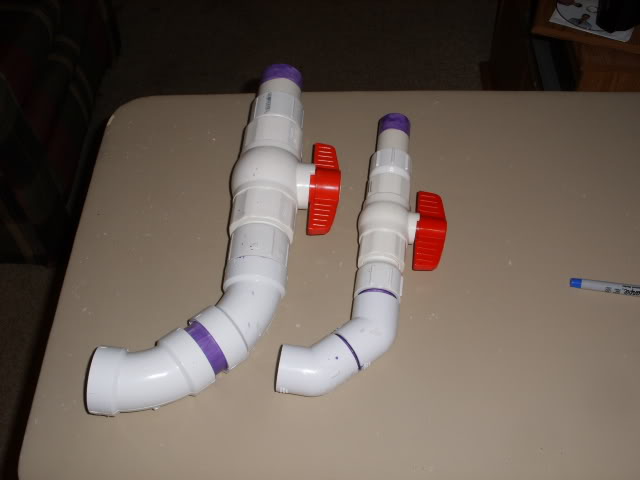
I have completed my flow design and have a MagDrive#24, intake strainers and ball valves in the mail.
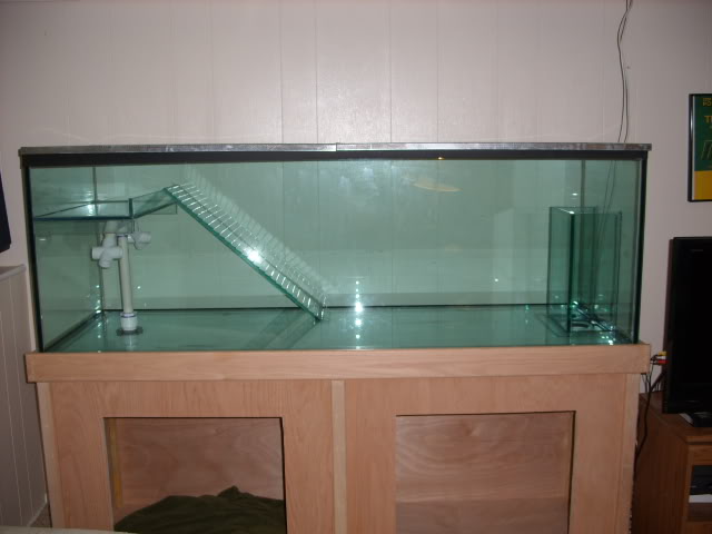
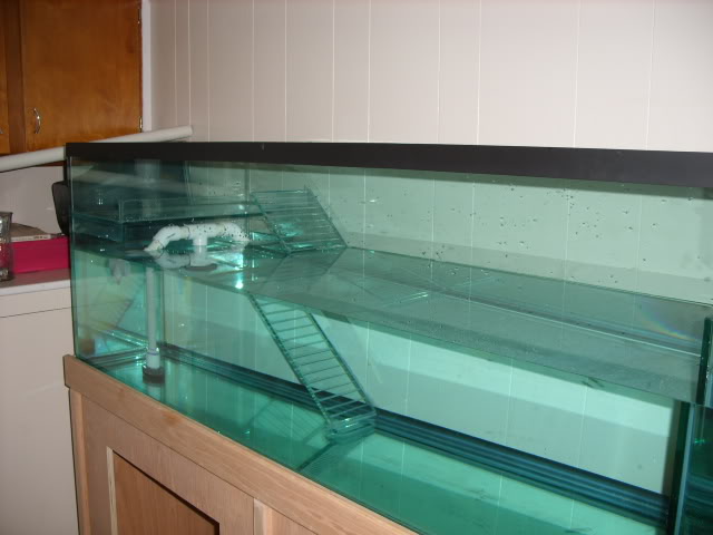
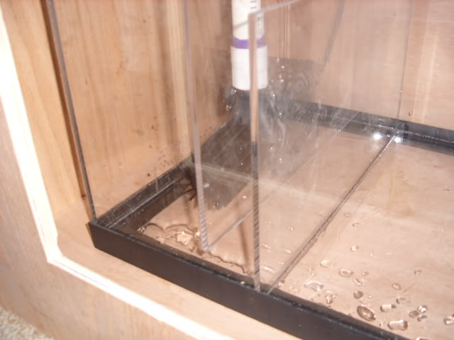
Here is a diagram of how the tank was built/drilled:
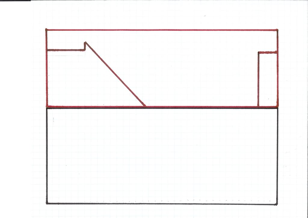
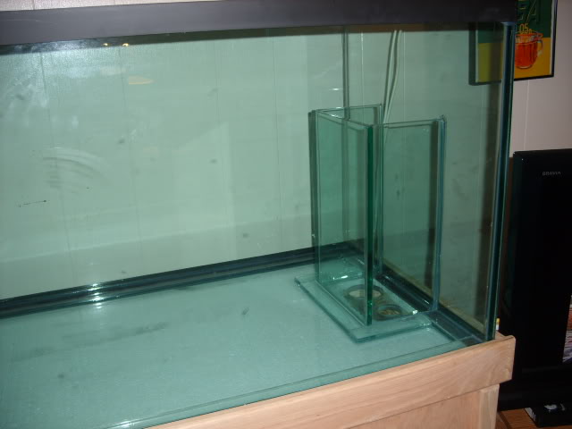
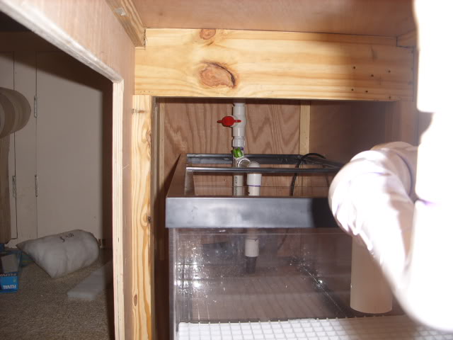
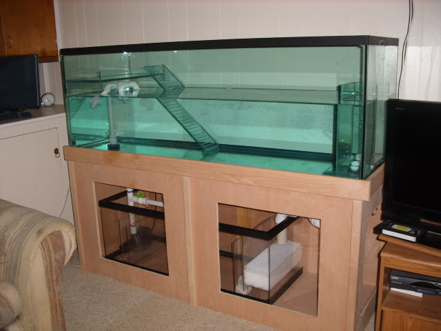
There is a lowered platform I will add rocks to, built in ramp, and overflow box which sets the water level 1/2" below the platform. There are holes drilled in the overflow box allowing 1" and 1.5" pipes. Underneath the platform is a hole allowing a 1.5" pipe that I intended to use as an intake for Fluval 405... but then I learned about potential siphoning and flooding during a power outage.
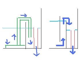
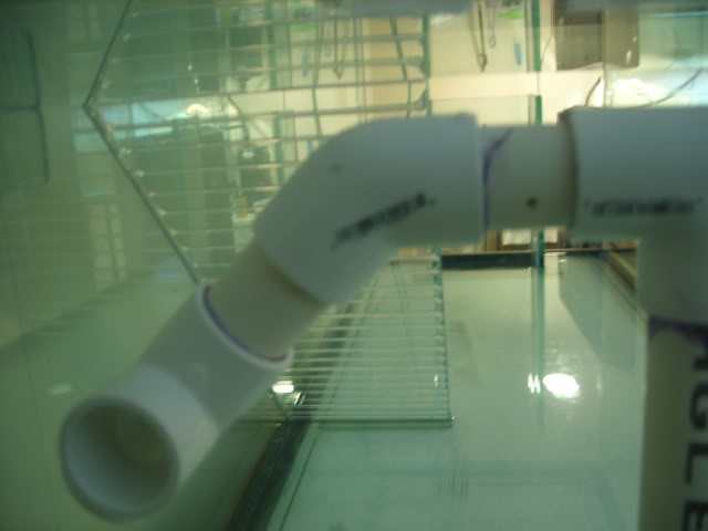
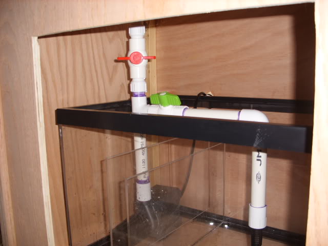
Here is a diagram including the equipment:
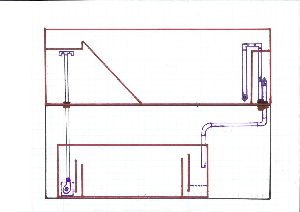
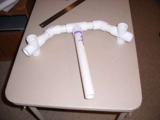
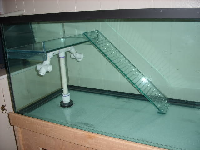
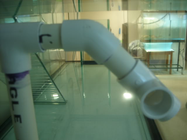
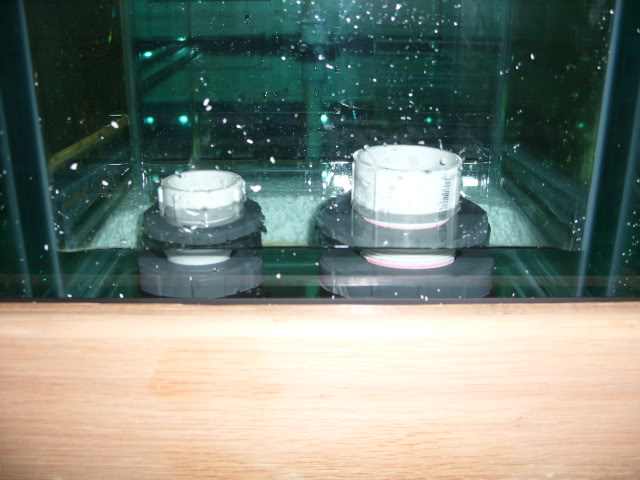
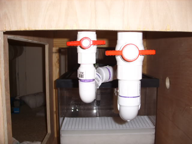
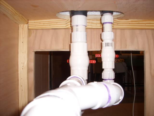
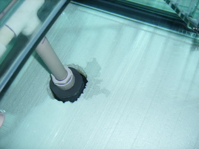
The hole under the platform will let the return line through, ending in a manifold at the surface facing in multiple directions to enhance flow accross the tank. The 1.5" pipe will have a strainer and the 1" will be a U over the lip of the overflow that will draw from the bottom of the display:
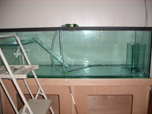
The diagram shows siphon breaking holes on the pipe in the box, though I have changed that to just below the surface in the display. I will add the holes 1 by 1 as too few wont break the siphon and too many will dominate the flow into the pipe.
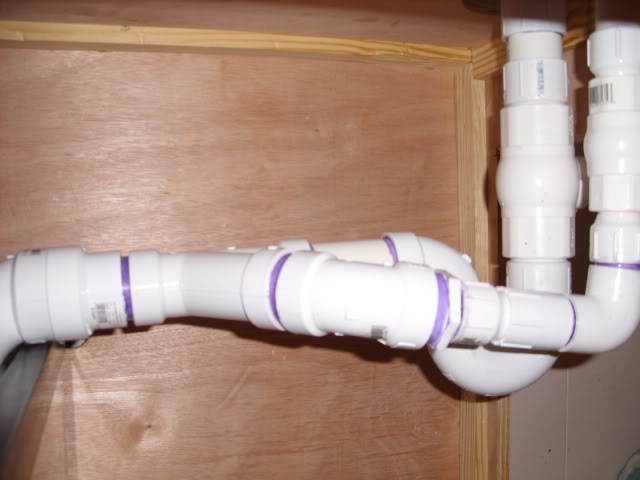
I am not sure whether this flow will be created/maintained by the Fluval or simply a gravity induced siphon initiated by opening a ball valve, whichever rate of flow is highest I guess is the one I will go with, it would be easier using the Fluval on the sump only anyway.
I'd appreciate feedback and sugestions, I will post photos of the build as I go over the next week or so.
I have completed my flow design and have a MagDrive#24, intake strainers and ball valves in the mail.
Here is a diagram of how the tank was built/drilled:
There is a lowered platform I will add rocks to, built in ramp, and overflow box which sets the water level 1/2" below the platform. There are holes drilled in the overflow box allowing 1" and 1.5" pipes. Underneath the platform is a hole allowing a 1.5" pipe that I intended to use as an intake for Fluval 405... but then I learned about potential siphoning and flooding during a power outage.
Here is a diagram including the equipment:
The hole under the platform will let the return line through, ending in a manifold at the surface facing in multiple directions to enhance flow accross the tank. The 1.5" pipe will have a strainer and the 1" will be a U over the lip of the overflow that will draw from the bottom of the display:
The diagram shows siphon breaking holes on the pipe in the box, though I have changed that to just below the surface in the display. I will add the holes 1 by 1 as too few wont break the siphon and too many will dominate the flow into the pipe.
I am not sure whether this flow will be created/maintained by the Fluval or simply a gravity induced siphon initiated by opening a ball valve, whichever rate of flow is highest I guess is the one I will go with, it would be easier using the Fluval on the sump only anyway.
I'd appreciate feedback and sugestions, I will post photos of the build as I go over the next week or so.