There were some folks interested in this process, so here is an overview of the build on my LED fixture.
Recently, I converted my freshwater planted 12 gallon long aquarium into a saltwater reef tank. However, I had a specific challenge in that it is not an easy tank to light.
I wanted an LED solution that employed powerful diodes, and was a controllable/dimmable fixture. Unfortunately, I could not find a commercially available solution that met these criteria.
So, I decided to build my own.
I started by designing the fixture and the stand to hold it. This tank is a unique challenge in that it is 36" wide, but very shallow. I decided 1 row of diodes would be more than sufficient to adequately cover the tank. Here are the plans I put together:
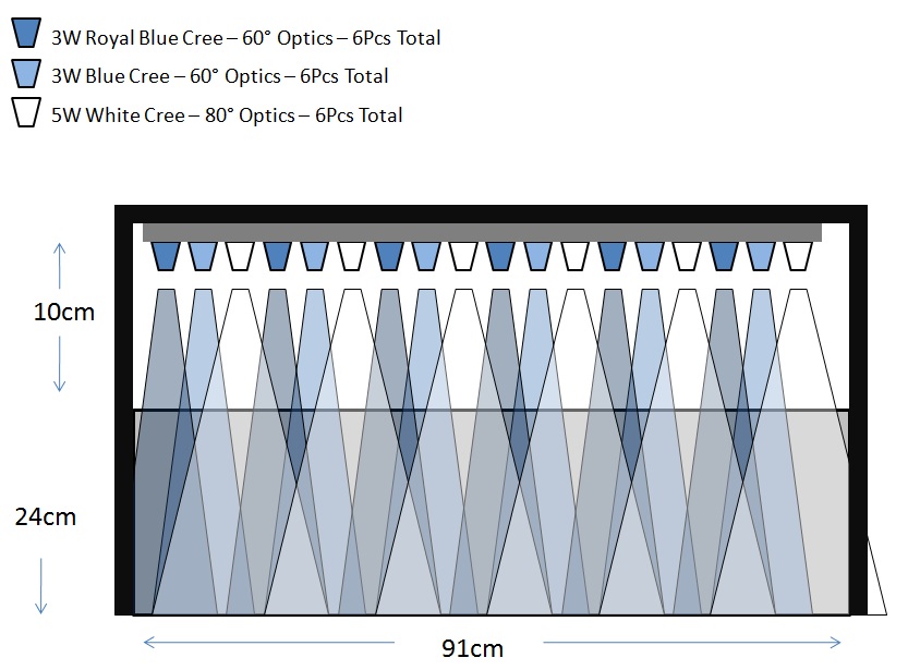
I started by figuring out the color mix and optics. On my larger reef tank, my lighting is quite white (by design). It is around 12,000K. For this tank, since I specifically hope to keep rare species of zoas, I wanted a bit more blue. I decided on a mix of 6 3W royal blue diodes, 6 3W blue diodes, and 6 5W cool white diodes. The blue and royal blue LEDs have 60 degree optics, while the whites have wider, 80 degree optics.
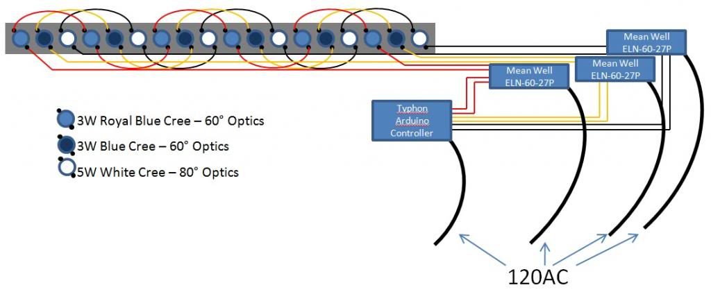
From there it was on to understanding how the system would be setup and ran. Wiring LEDs is quite simple - you just wire them in series from + to -, and back around at the end to complete the circuit. However, I wanted to add some control to the system. While the drivers are capable of driving far more than 6 LEDs, I decided to put each color on it's own driver so that I could fine tune the lighting. The drivers are in turn controlled by an arduino based Typhon LED controller from BoostLED. It sends a signal between 1-10Vs to the drivers which then drive the LEDs accordingly (1V = 10% intensity, 2V=20%, and so on).
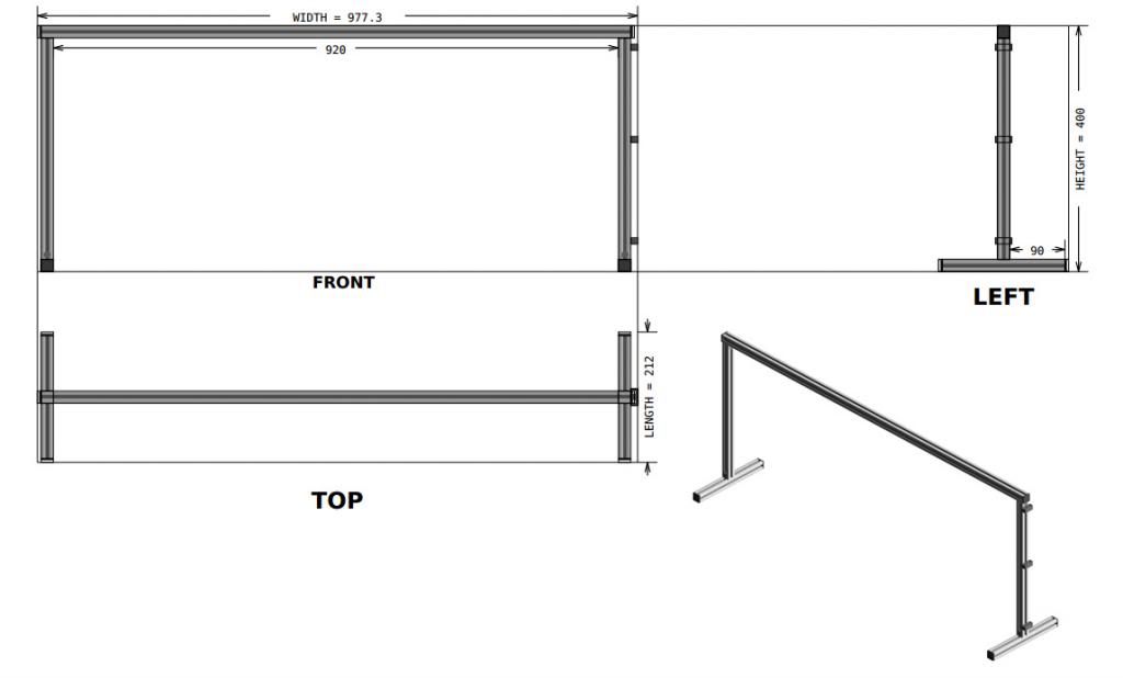
The next area of design was for the stand. I found a great resource for this at framexpert.com. They have a downloadable and free design program that makes designing any aluminum frame a simple task. Here is what I came up with for my design for the stand:
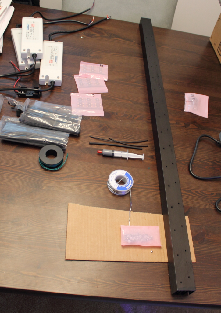
Once all parts arrived, it was just a matter of assembly. I ordered most of the LED components (besides the controller) from RapidLED.
First, the heat sink: I went with a pre drilled/tapped 36".
The LED's are screwed onto the heat sink, after a small amount of thermal grease is applied to the underside of the LED PCB. Since the LED's aren't really discernible (they all look alike for the most part), I had to be very careful not to mix any of them up, both in laying them out, and later when wiring them.
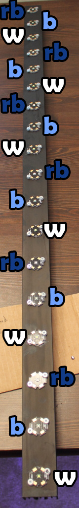
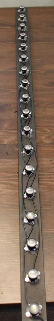
Once screwed down, it is just a matter of wiring each string in series, + to -. The optics are then glued in place over the diode:
I used Mean Well drivers for the build - the 27P was more than powerful enough to run my 6 string circuits. The Typhon controller requires PWM input, so driver choice was limited. RapidLED has plenty of documentation on the subject, but if you intend to build your own dimmable fixture, be sure to turn down your SVR2 before connecting power to the LEDs. Otherwise, you risk blowing them all up, which would an expensive mistake. The wiring portion seems a bit intimidating at first, especially if you are not an experienced electrician or tinkerer, but really with RapidLED's documentation, it is not all that difficult. You just need some #22 wire (I got mine at radio shack), some good wire strippers, a soldering iron, some rosen core lead solder, and a multimeter to adjust the SVR2 current. Basically, you connect 1 end of the driver to power, and the other end has a + and - that goes to the LED string, and a + and - that goes to your voltage source for dimming/control.
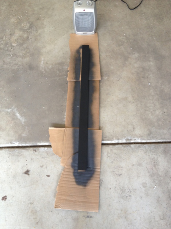
Once the optics were all installed and the fixture wired up, I added a piece of 1/4" stock aluminum to the front to shield the LEDs from the room. I just spray painted it black to match the heat sink:
I then used some good strong epoxy to attach it to the front of the heat sink:
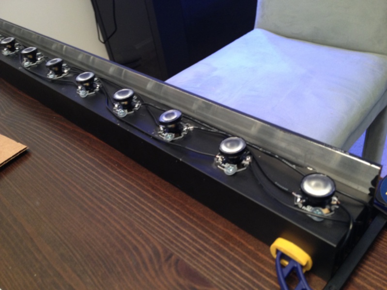
After assembling the stand and putting some finishing touches on hiding the wiring in the t channel aluminum of the stand, the fixture was ready to go:
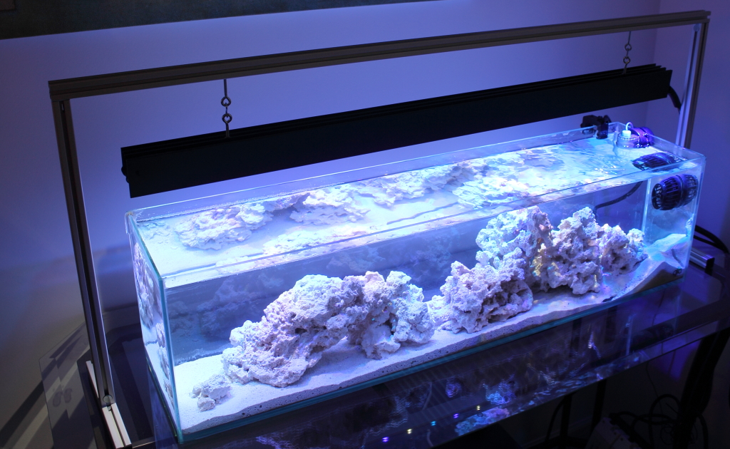
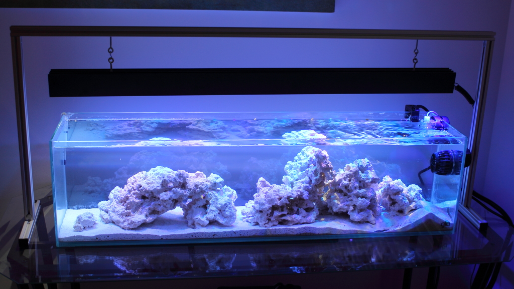
If anyone has any questions, or comments, let me know! Overall, it was a fun build that was not too challenging - probably 4-6 hours of total time, and someone with more soldering skills could do it in less time than that. The wiring can be a bit intimidating upfront, but with RapidLED's documentation, I had a clear understanding of what to do going into the project. Total cost for the build was far less than buying any COTS controllable fixture, especially when given the size constraints this particular tank has.
Recently, I converted my freshwater planted 12 gallon long aquarium into a saltwater reef tank. However, I had a specific challenge in that it is not an easy tank to light.
I wanted an LED solution that employed powerful diodes, and was a controllable/dimmable fixture. Unfortunately, I could not find a commercially available solution that met these criteria.
So, I decided to build my own.
I started by designing the fixture and the stand to hold it. This tank is a unique challenge in that it is 36" wide, but very shallow. I decided 1 row of diodes would be more than sufficient to adequately cover the tank. Here are the plans I put together:
I started by figuring out the color mix and optics. On my larger reef tank, my lighting is quite white (by design). It is around 12,000K. For this tank, since I specifically hope to keep rare species of zoas, I wanted a bit more blue. I decided on a mix of 6 3W royal blue diodes, 6 3W blue diodes, and 6 5W cool white diodes. The blue and royal blue LEDs have 60 degree optics, while the whites have wider, 80 degree optics.
From there it was on to understanding how the system would be setup and ran. Wiring LEDs is quite simple - you just wire them in series from + to -, and back around at the end to complete the circuit. However, I wanted to add some control to the system. While the drivers are capable of driving far more than 6 LEDs, I decided to put each color on it's own driver so that I could fine tune the lighting. The drivers are in turn controlled by an arduino based Typhon LED controller from BoostLED. It sends a signal between 1-10Vs to the drivers which then drive the LEDs accordingly (1V = 10% intensity, 2V=20%, and so on).
The next area of design was for the stand. I found a great resource for this at framexpert.com. They have a downloadable and free design program that makes designing any aluminum frame a simple task. Here is what I came up with for my design for the stand:
Once all parts arrived, it was just a matter of assembly. I ordered most of the LED components (besides the controller) from RapidLED.
First, the heat sink: I went with a pre drilled/tapped 36".
The LED's are screwed onto the heat sink, after a small amount of thermal grease is applied to the underside of the LED PCB. Since the LED's aren't really discernible (they all look alike for the most part), I had to be very careful not to mix any of them up, both in laying them out, and later when wiring them.
Once screwed down, it is just a matter of wiring each string in series, + to -. The optics are then glued in place over the diode:
I used Mean Well drivers for the build - the 27P was more than powerful enough to run my 6 string circuits. The Typhon controller requires PWM input, so driver choice was limited. RapidLED has plenty of documentation on the subject, but if you intend to build your own dimmable fixture, be sure to turn down your SVR2 before connecting power to the LEDs. Otherwise, you risk blowing them all up, which would an expensive mistake. The wiring portion seems a bit intimidating at first, especially if you are not an experienced electrician or tinkerer, but really with RapidLED's documentation, it is not all that difficult. You just need some #22 wire (I got mine at radio shack), some good wire strippers, a soldering iron, some rosen core lead solder, and a multimeter to adjust the SVR2 current. Basically, you connect 1 end of the driver to power, and the other end has a + and - that goes to the LED string, and a + and - that goes to your voltage source for dimming/control.
Once the optics were all installed and the fixture wired up, I added a piece of 1/4" stock aluminum to the front to shield the LEDs from the room. I just spray painted it black to match the heat sink:
I then used some good strong epoxy to attach it to the front of the heat sink:
After assembling the stand and putting some finishing touches on hiding the wiring in the t channel aluminum of the stand, the fixture was ready to go:
If anyone has any questions, or comments, let me know! Overall, it was a fun build that was not too challenging - probably 4-6 hours of total time, and someone with more soldering skills could do it in less time than that. The wiring can be a bit intimidating upfront, but with RapidLED's documentation, I had a clear understanding of what to do going into the project. Total cost for the build was far less than buying any COTS controllable fixture, especially when given the size constraints this particular tank has.