PVC overflow assembly

The friendliest place on the web for anyone with an interest in aquariums or fish keeping!
If you have answers, please help by responding to the unanswered posts.

dskidmore

Aquarium Advice Addict
Joined
Aug 21, 2005
Messages
2,616
Location
Genesee Valley
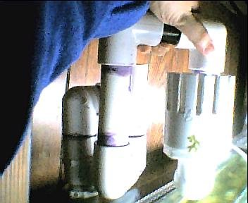
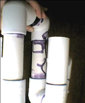
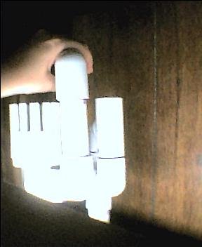
Ok, I made this assembly from 1" PVC, with a 2" inlet strainer. According to calculations I got elswhere, it should have been able to take around 600 GPH. I'm actually getting around 90 GPH. Any ideas what went wrong?

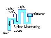
P.S. Concept drawing attached now too.
 

Attachments

  • overflowassembly.jpg
    overflowassembly.jpg
    18.1 KB · Views: 799
  • overflow_concept_diagram.jpg
    overflow_concept_diagram.jpg
    5.2 KB · Views: 767
You can just barely see on the first picture in the back left the T that is the siphon break. There is no other leak/opening.

Here's a couple more views from my crummy camera.
 

Attachments

  • overflow_view_2.jpg
    overflow_view_2.jpg
    11.8 KB · Views: 730
  • overflow_view_3.jpg
    overflow_view_3.jpg
    11.7 KB · Views: 756
I seem to thing that all those 180 degree turns have a poor effect on those designs.. but there are some other members that have worked on these.. Hope you can get some help.. From what Ive read there has been some trouble working with these..

the only issue I can think of is all the turns and that maybe the syphon break isnt at the exact level to keep flow as high as it could be.. sorry I cant be more help on this one.. :?
 
It's only $13 worth of parts, as opposed to the $80 for the professional one. Even if I have to try again it's worth it, and I've learned something too.

Next one is made from threaded parts, so I can add in more length to the pipes when necessary.

At least the temporary filter is holding the ammonia and nitrites at 0. (Bucket of gravel, lift tube, air pump. Looks mighty unsightly in my aquarium.)
 
Back
Top Bottom