JohnS
Aquarium Advice Regular
Very interesting thread. Thanks all for the info so far.
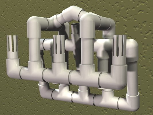
I'm thinking about using something like this to tie my 20g qt into a 30g garbage can (effectively giving my new fish 50g). Since I'm going with a smaller application, do you think I could build it with smaller diameter PVC? or would it be smarter to redesign it using fewer drains/ports? I'll probably use my Mag 7 as the return ph.
Any thoughts?
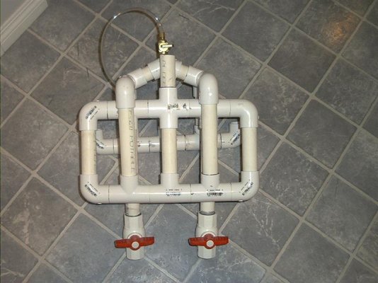
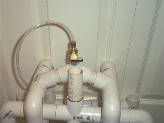
") . Our in-tank legs right now are the same length as our back lines. The picture of the valve is great. What do you figure the theory is behind that spout that goes up that is open? That makes so little sense to me! Seems like air would get into the system through that when you shut it off. We actually covered ours in an attempt to get it to keep running (before I posted here) to no avail.
. Our in-tank legs right now are the same length as our back lines. The picture of the valve is great. What do you figure the theory is behind that spout that goes up that is open? That makes so little sense to me! Seems like air would get into the system through that when you shut it off. We actually covered ours in an attempt to get it to keep running (before I posted here) to no avail.