Bearfan's Auto-Topoff Documentation

The friendliest place on the web for anyone with an interest in aquariums or fish keeping!
If you have answers, please help by responding to the unanswered posts.

Bearfan

Aquarium Advice Addict
Joined
Dec 30, 2002
Messages
3,967
Location
Franklin, TN
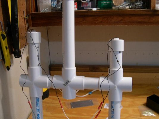
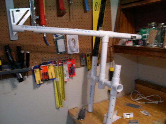
It's finally completed.

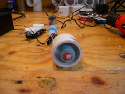
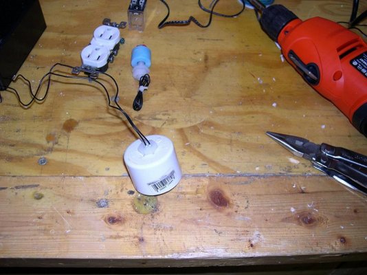
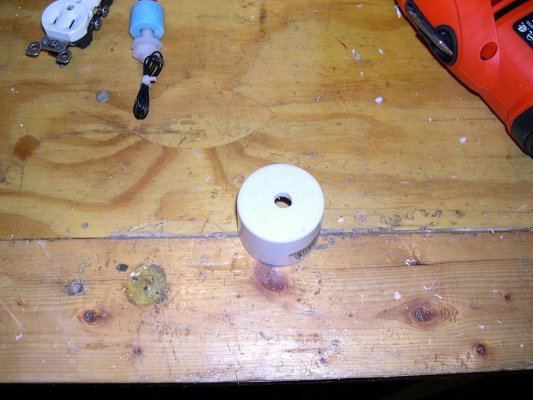
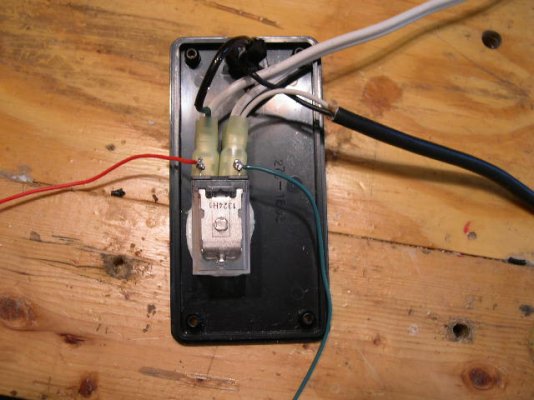
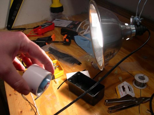
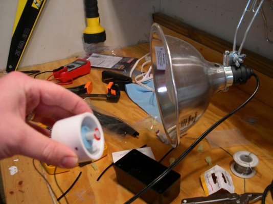
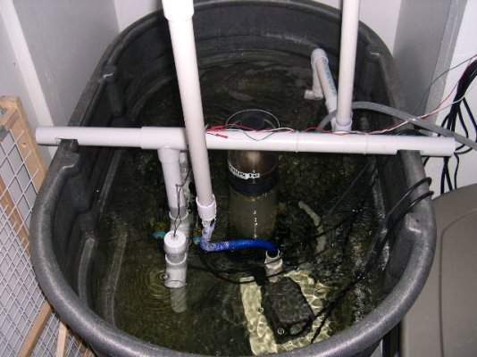
These first three pictures show the installation of the float into a standard 1-1/4" PVC cap. What it doesn't show is the second hole I ended up drilling in each one to allow for air to escape. It also doesn't show the dab of silicone I put at the wire connections just in case.

Floats are from Floatswitches.net

PVC is from Menards
 

Attachments

  • dscn1427.jpg
    dscn1427.jpg
    70.8 KB · Views: 194
  • dscn1423.jpg
    dscn1423.jpg
    94.1 KB · Views: 98
  • dscn1420.jpg
    dscn1420.jpg
    93.9 KB · Views: 177
Next I took an extra computer power cable (The black cable) and extension cord (the white cable) and cut the ends not shown off. I stripped back the outer covering on each to expose the wires, snipped the ground wire off of the black cable (it's on a GFCI) and stripped the connections.

I took a project box and installed a 120V switch. I wired the positive wire to the switch and soldered the connection. I added a small jumper to the other side with a quick connect and installed quick connectes on the other 3 wires.

Computer Cable and Extension cords were extra I had
Project Box, Connectors and Switch from Radio Shack
 

Attachments

  • dscn1437.jpg
    dscn1437.jpg
    93.3 KB · Views: 92
  • dscn1434.jpg
    dscn1434.jpg
    66 KB · Views: 174
  • dscn1481.jpg
    dscn1481.jpg
    73.2 KB · Views: 81
Next I took and epoxyed the relay onto the project box and allowed to sit overnight. I connected the wires from the power cable and the outlet cable to the respective spots (see wiring diagram)

I wired a 12VDC transformer to the float switches as also shown in the wiring diagram.

Relay from Radio Shack
DC Transformer was an extra I had.
 

Attachments

  • dscn1462.jpg
    dscn1462.jpg
    68.9 KB · Views: 106
  • wiring.jpg
    wiring.jpg
    16.8 KB · Views: 383
  • dscn1492.jpg
    dscn1492.jpg
    81.2 KB · Views: 100
Now the moment of truth. I powered it up and pluged in a lamp to check the floats were functioning.
 

Attachments

  • dscn1456.jpg
    dscn1456.jpg
    80.8 KB · Views: 109
  • dscn1454.jpg
    dscn1454.jpg
    78.1 KB · Views: 175
Time to build the rig. I measured all of the PVC and cut as shown. The verticle risers have holes drilled so water can enter the tube without problems. The lower riser is the normal operating float, the higher riser is if the lower riser ever stuck in the on position, it would break the circuit and prevent excess RO from entering the system.
 

Attachments

  • dscn1489.jpg
    dscn1489.jpg
    73.9 KB · Views: 98
  • dscn1482.jpg
    dscn1482.jpg
    76.4 KB · Views: 192
And the final assembly (completed this morning, the wires are going to be cleaned up soon!)

A Maxi-Jet 1200 is connected to the tubing into the sump (above the water level to prevent reverse syphon) and the line in is from the RO/DI unit.
 

Attachments

  • dscn1493.jpg
    dscn1493.jpg
    86 KB · Views: 115
  • dscn1495.jpg
    dscn1495.jpg
    76.6 KB · Views: 191
Back
Top Bottom